Mastering High Temperatures: The Essential Guide to G-Fin Embedded Finned Tubes


In the intense world of industrial thermal engineering, efficiency is everything. When process temperatures soar above 250°C (480°F), standard “tension-wound” finned tubes simply can’t handle the stress. They loosen, gaps form, and heat transfer efficiency plummets.
This is where the G-Fin Embedded Finned Tube (often called the “Grooved Fin”) proves its worth. Designed specifically to bridge the gap between moderate-temperature capability and high-temperature durability, the G-Fin is the workhorse of heavy industry.
But what makes the “embedding” process unique, and why is it considered the best practice for high-stakes thermal applications? This comprehensive guide explores the technology, the critical advantages, and the diverse applications of G-Fin tubes.
What is a G-Fin Embedded Finned Tube?
The “G” in G-Fin stands for “Grooved.” Unlike fin types that are simply wrapped around the surface of a tube, the G-Fin is mechanically locked into the tube wall itself.
The Critical Manufacturing Process
The integration of the fin and the tube is a precise, multi-step engineering feat:
-
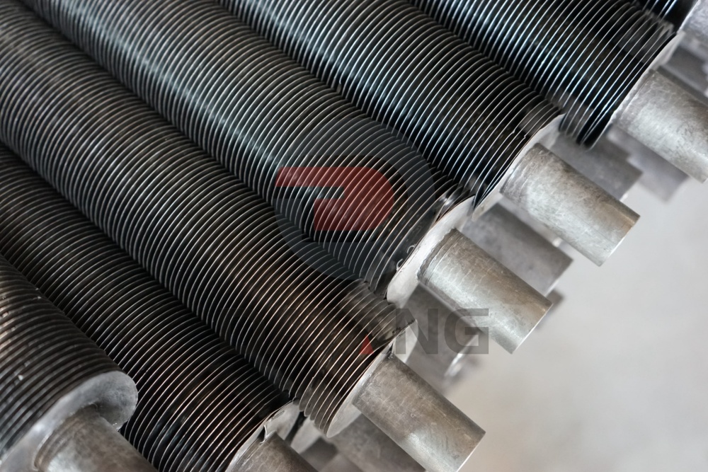
Plowing the Groove: A specialized machine accurately “plows” a spiral groove into the outside surface of the base tube. Critically, this process displaces material but does not remove it, maintaining the tube’s structural integrity.
-
Inserting the Fin: A continuous metal strip (usually aluminum or copper) is wound under high tension directly into this newly created groove.
-
Mechanical Locking: The displaced tube material is then backfilled and compressed against the side of the fin. This creates a powerful, permanent mechanical bond.
This process ensures that the fin is not just “sitting on” the tube, but is truly “part of” the tube, maximizing thermal conductivity.
Technical Specifications and Material Synergy
The strength of a G-Fin tube lies in its ability to combine different materials to handle internal pressure and external heat transfer simultaneously.
-
Base Tube Material: Carbon Steel (e.g., A179, A192, A106 Gr B), Stainless Steel (e.g., 304, 316, 321), or Copper-Nickel alloys. This handles the corrosive fluid and high internal pressure.
-
Fin Material: Aluminum or Copper. These metals provide exceptional thermal conductivity, crucial for efficient heat dissipation to the surrounding gas/air.
-
Operating Temperature: This is the G-Fin’s superpower. While L-Foot fins fail around 130°C, G-Fins operate reliably up to 400°C (750°F).
-
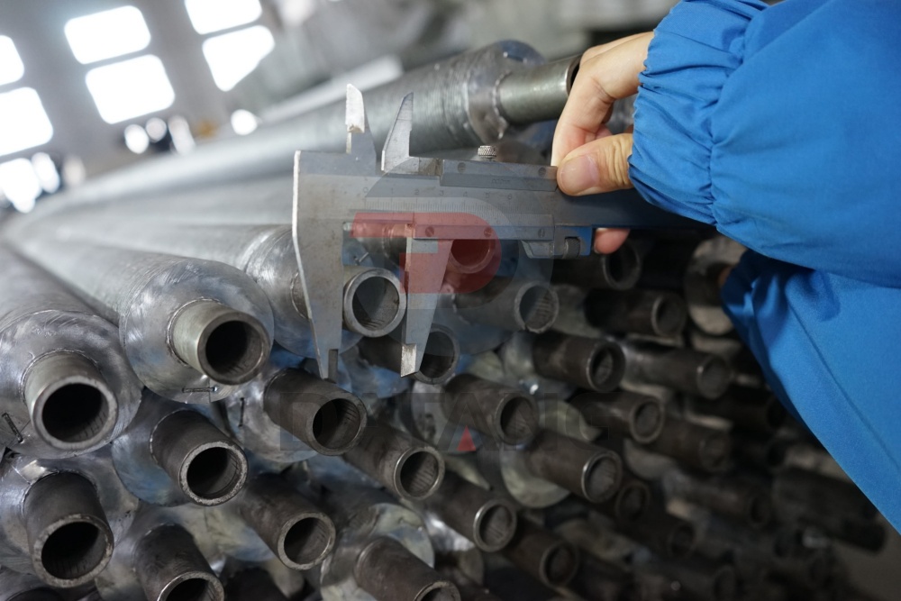
Standard Dimensions: Tube ODs often range from 15.8mm to 50.8mm, with fin heights up to 16mm and pitches customized to the specific air-flow requirements.
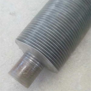
[Image detail of the G-Fin root, showing the locking mechanism]
Top 5 Advantages of G-Fin Technology
Why do engineers specify G-Fins for critical power generation and petrochemical infrastructure? The decision boils down to performance under duress.
1. Exceptional Thermal Stability at High Temperatures
As a heat exchanger heats up, the fins and the base tube expand at different rates. In tension-wound designs, this thermal cycling causes the fin to “pull away,” creating a microscopic air gap that acts as an insulator. The G-Fin’s embedded bond remains tight, ensuring consistent heat transfer across thousands of start-stop cycles.
2. High Mechanical Strength and Durability
The embedding process creates a root that is exceptionally robust. G-Fin tubes can withstand rigorous maintenance, including high-pressure water jetting or soot blowing to remove fouling, without the fins flattening or detaching. This is vital in industries where uptime is mandatory.
3. Maximum Heat Transfer Efficiency
With 100% metal-to-metal contact at the fin root and no air gap, the thermal resistance is minimized. This allows engineers to design smaller, more efficient heat exchanger banks, reducing the overall footprint and material costs of the project.
4. Resistance to Vibration
Many industrial environments, such as power plants or compressor stations, experience significant mechanical vibration. The G-Fin’s locked design ensures the fins will not vibrate loose, preventing catastrophic failure of the cooling bundle.
5. Predictable Long-Term Performance
Because the bond between the fin and tube does not degrade with time or temperature (up to its design limit), the G-Fin offers predictable performance. Facility managers can rely on the heat exchanger’s output, simplifying process control and energy calculations.
Key Application Fields
The unique capabilities of G-Fins make them indispensable in several high-stakes engineering sectors:
1. Petrochemical and Refining
In oil refineries, G-Fins are critical components in Air Cooled Heat Exchangers (ACHE), often used to cool hot process streams, gases, or condensed vapors. Their ability to handle high process inlet temperatures and resist severe external environments is essential.
2. Power Generation
They serve as critical elements in Boiler Economizers and Air Pre-heaters. By recovering waste heat from hot flue gases (often 300°C+), they boost overall boiler efficiency, saving fuel and reducing emissions. They are also used extensively in heat recovery steam generators (HRSG) for combined cycle power plants.
3. Waste Heat Recovery (WHR) Systems
Industries with hot exhaust streams—such as glass manufacturing, cement production, or steel milling—use G-Fin heat exchangers to capture energy and convert it into hot water or electricity (Organic Rankine Cycle).
4. Gas Compression
Large compressor stations utilize G-Fins in intercoolers and aftercoolers to manage the heat generated during gas compression.
Engineering Considerations: Standard vs. Heavy-Duty
When specifying G-Fins, it’s vital to consider the environment. While aluminum fins offer the best thermal/weight ratio, copper fins provide even higher thermal conductivity and superior corrosion resistance in specific chemical atmospheres. Additionally, tube wall thickness must be sufficient to accommodate the depth of the groove (often around 0.4mm to 0.8mm) while still meeting pressure vessel codes.
Conclusion: Investing in High-Temperature Reliability
Choosing the right finned tube is an engineering decision, not a purchasing one. For medium-to-high temperature applications in demanding environments, the G-Fin Embedded Finned Tube is the standard for long-term reliability.
By prioritizing a permanent, mechanically locked bond, you guarantee thermal efficiency, durability, and a lower total cost of ownership. The G-Fin isn’t just a component; it’s the anchor of a stable, efficient thermal process.